Headlamp Relay
This method replaces the bulb's power with heavy wiring and relays in the engine compartment. The original wiring under the dash remains untouched.
Turn on the lights and use a test light to find out which color wire goes to which bulb terminal. You will need to know which is high and which is low beam. The dash indicator determines this later. Write them down for future reference. Keep track of which wire goes to what bulb terminal also.
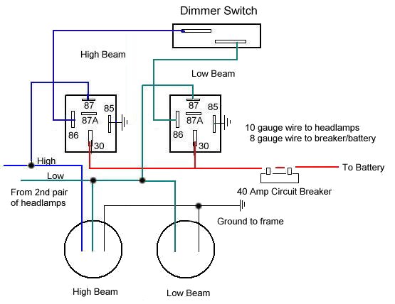
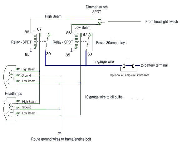
Cut the wires going to the headlight bulbs and reroute them to each relay's terminal 86. Ground each relay's terminal 85. This makes the headlight and dimmer switches contact controllers with a very low current draw. The old headlight and dimmer switches will keep going as long as the mechanical action lasts, because arcing and heating of the switch contacts disappear with this project.
Turn on the lights and operate the dimmer switch. You should hear clicking noises from the relays. Watch the dash indicator and leave the lights on high beam. Use a test light to see which relay is on. Mark this relay "High Beam." (You should already know which relay is high beam if you wrote the wire colors down first).
Solder an 8 gauge wire to two short pieces of 10 gauge wire. Use tape or heat shrink to finish the splice. Connect these to terminal 30 of each Bosch relay. Route the 8 gauge wire to the battery. You may have to purchase a battery terminal to enable the 8 gauge wire to attach to the battery itself. You also might want to put a 40 amp breaker close to the battery. An alternate method is to tap onto the big wire going to the starter terminal. Don't power up the 8 gauge wire before you get the relay end done, unless you like fireballs in your face should it touch the frame!
Run 10 gauge wires from each relay's terminal 87 to the head lamp bulbs. The best way is to remove the old wires from the bulb sockets by pushing in the tab "ear" from the side to get the connector out. On some sockets, you will need a skinny tool pushed down along the terminal from the front of the socket to push down the tab. Solder the high/low wires to the connectors. Replace the ground wires with 10 gauge while you're at it. This avoids the crappy looking 1" splice at the bulb socket. Be sure of which terminal is what before you tear them apart. You can solder the wires together at the bulb, and run the set to the other light bulb. You will have to split the 10 gauge wiring somewhere to feed the two sides. Scope out the vehicle for the best way to route them.
The ground wires should be run to the alternator bracket or other really solid grounding point. Don't cut corners on grounding the light bulbs or you will end up with a "yellow light" problem. After you are done you should have much brighter lights. The resistance of the new wiring is going to be a lot less than it ever was from the factory.
High Beam & Low Beam Dual Headlamps

Single Headlamps


