
 1964 Chevelle
 1965 Chevelle
 1966 Chevelle
 1967 Chevelle
 1968 Chevelle
 1969 Chevelle
 1970 Chevelle
 1971 Chevelle
 1972 Chevelle
![]()
HEI Conversions
Finding an HEI Distributor
There are a couple of choices here, new or used. In addition, here are a few things to note:
- '75 to '79 ('75 to '85 Canadian) used 4-pin modules.
- Some later models used a 5-pin module (for a knock sensor)
- Computer controlled engines used a 7-pin module
When replacing a points distributor, you should use a distributor with the 4-pin module. You could also use a distributor with a 5-pin module and replace the module with a 4-pin one. That would require plugging the extra hole in the housing where the connector for the knock sensor wiring used to be. Distributors using 7-pin modules can not be converted to non-computer controlled use since they do not have advance mechanisms (they use the computer to control the advance).
Also note that different GM divisions used distributors with different shafts and gears. So make sure that your used distributor came from the same type of engine that you plan to install it in.
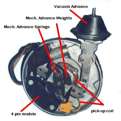
Rebuilding a Used Distributor
If you choose to re-build a used distributor, here are a few suggestions/ideas:
- The drive gear is held on by a roll pin -- carefully drive out the pin with a punch to remove the gear.
- Once the gear is off, the shaft should slide out. If it doesn't, there is probably a rust build up on it. Use some penetrating oil and work carefully to avoid damaging the bushings.
- Once the distributor is fully dis-assembled, thoroughly clean everything.
- Inspect for damage (particularly the pick-up coil & wires) and replace parts as necessary.
- Slide the shaft into the housing and check for excessive play between the shaft and bushings. New bushings (or another housing with better bushings) may be necessary.
- After re-assembly of the gear on the shaft, slide it end-to-end and use a feeler gauge to check for excessive end play. Use shims as necessary to get the axial end play near 0.015".
- Also check the mechanical advance and make sure that it is working freely.
- The factory advance in HEI distributors used very stiff springs resulting in a very slow mechanical advance. Pick up an advance curve kit that contains various springs so you can experiment with re-curving the distributor.
- Finally, finish the re-assembly with a new rotor and cap.
Physical Installation
Here is where firewall clearance problems can make things difficult. You may have to modify your firewall to clear the HEI's larger cap. In any case, measure to make sure that it will fit. The air cleaner housing may also present a clearance problem as well.
Primary Wiring
The power supply for the breaker point distributor is routed through a resistance wire to drop the voltage and prevent damage to the points. A bypass wire was also used to supply the distributor with a full 12 volts at startup. On the other hand, an HEI distributor requires a full 12 volt supply. This can be accomplished by replacing or bypassing the resistor wire. In order to achieve a factory look, use a supply wire from a donor vehicle (such as an '80 Chevy truck). To install this wire, carefully remove the terminal end from the bulkhead connector on the truck. Next, remove the resistor wire terminal end from the bulkhead connector. Then, plug the wire from the truck into the bulkhead connector. After taping up the end of the resistor wire and routing the new wire inside the wire loom, you are finished.
>Here are a couple diagrams illustrating the wiring of the points and HEI ignition systems. The first diagram shows a typical stock points system. The second diagram shows where the wires go when converting to HEI. Note that the new HEI power wire can be connected to the bulkhead connector as described in the above paragraph, or it can be routed to the "IGN" terminal found on most fuse panels.
Wiring for Typical Points Ignition System
Wiring for Typical HEI Ignition System:
Another important issue is the combination of voltage regulator and HEI module that you are using. If you have a mechanical regulator (stock on pre-71), you may have problems with burnt out HEI modules. I've heard that many replacement HEI modules (especially the inexpensive ones) do not have built-in over voltage protection. To prevent problems, either use GM (or other quality) HEI modules, or change to a solid state voltage regulator.
![]() Mention you saw it on © ChevelleWorld and please give the site credit for the
information.
Mention you saw it on © ChevelleWorld and please give the site credit for the
information.
![]() Be sure to visit my ChevelleCD site for
Chevelle CDs, challenge coins, and other gifts for that Chevelle fan in your
family and my
Stickers & Calendars website for custom stickers and calendars with your
favorite car/pet/occasion.
Be sure to visit my ChevelleCD site for
Chevelle CDs, challenge coins, and other gifts for that Chevelle fan in your
family and my
Stickers & Calendars website for custom stickers and calendars with your
favorite car/pet/occasion.