Chassis, Suspension, and Brakes
Engine, Transmission, and Driveshaft
Moving on and if you have not already done so remove the engine,
transmission and driveshaft. Again, fully photo document everything
you disassemble. When the time comes to assemble you can refer back
to these photos to determine if parts were missing when you originally
disassembled everything, their location and placement and things
such as engine to bellhousing paint overspray just to name a few.
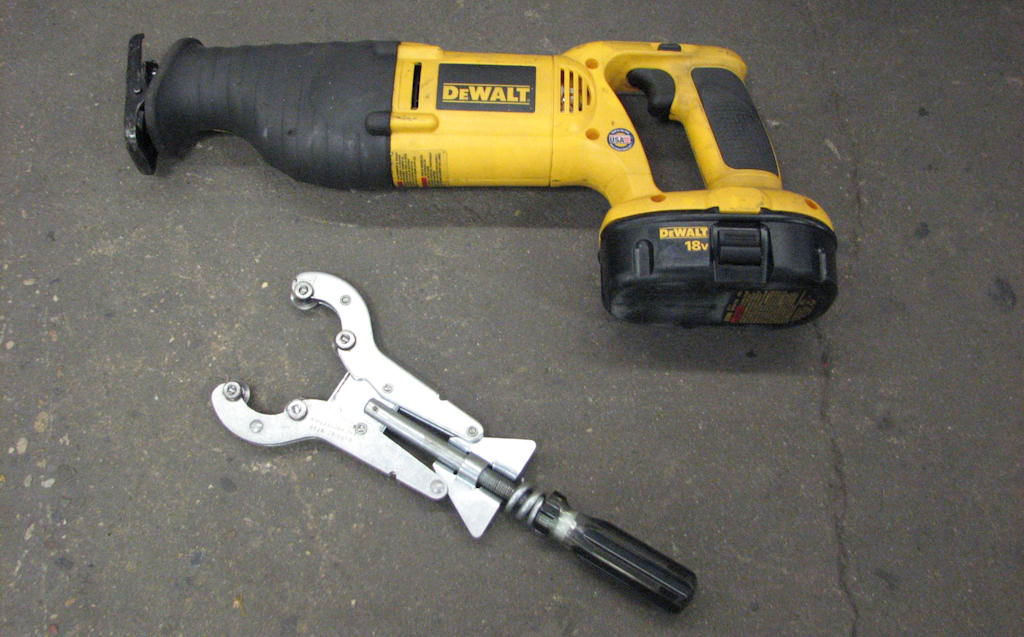
Either of these two tools will work well
to remove your old exhaust system. If you already own a Saws All that
is the quickest and easiest way to remove it. The exhaust pipe cut off
tool can be purchased for under $30 which is also a good alternative.
In a pinch simply use a hack saw.
Start by disconnecting any components related to the drivetrain
such as electrical, fuel lines, exhaust and any remaining transmission
or carburetor linkages. If you are saving your exhaust, and this
cannot usually be done very well, then carefully start by removing
the exhaust tips, tail pipes, mufflers and the head pipes. Once
those are removed proceed by removing all the hangers. If you do
not intend to save the exhaust then just cut them apart using a
tool such as a Saws All or exhaust cutter.
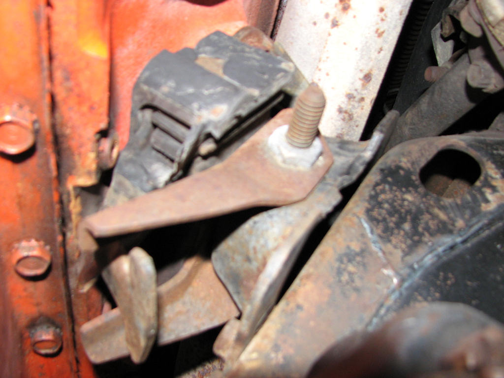
On assembly line engine mounts the nuts
are swaged onto the mount and do not require two tools when tightening.
If you no longer have the original mounts you can simulate this by using
thin nuts and orientating the bolts from back to front on the driver’s
side and front to back on the passenger side.
Unbolt the engine mount through bolts found on either side of the
engine. If this is an original or unmolested car, make note of the
direction of the bolts and motor mounts. Original assembly line
engine mounts had a swaged nut on one side of the engine mount allowing
the assembly worker to simply install the bolt through the mount
and not have to worry about putting a wrench on the nut on the other
side. Replacement mounts did not come with this and required installing
a nut and lock washer onto the bolt. However, when reassembling
the engine onto the frame you can still simulate factory mounts
by at the very least installing the bolts in the same direction
as the factory did. On the driver’s side the bolt was installed
from the rear towards the front. The passenger side is just the
opposite since it uses the same part numbered engine mount and the
bolt was installed into the front side of the mount.
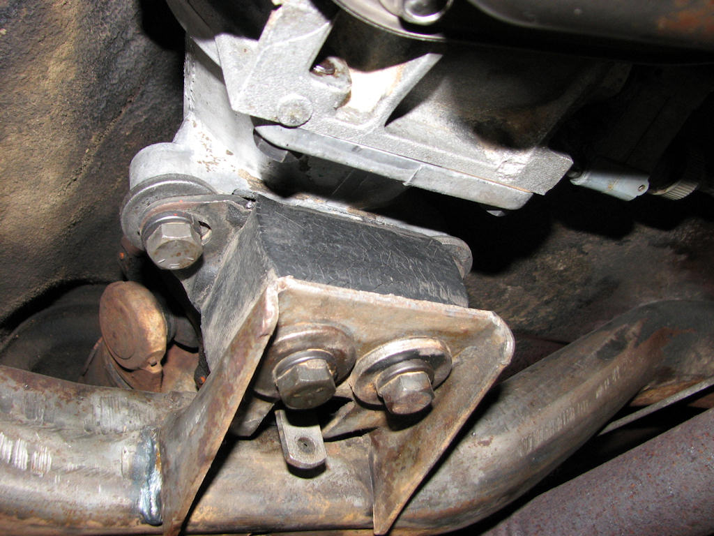
Note how there is a large washer installed
between the top of the transmission mount and the transmission tail
housing. This is only on automatic cars and must be put back in this
way as it affects the pinion angle. People often times install the large
washer under the lock washer and bolt on the top mount to tail housing
bolts and that would be incorrect.
Unbolt the two bolts that hold the transmission mount to the crossmember
be it a manual or automatic transmission. Take special note of how
the washers are placed on automatic transmission cars assuming it
has never previously been removed as two large washers should actually
be mounted between the transmission tail shaft housing and the transmission
mount on either side. This aids in pinion alignment and is very
important.
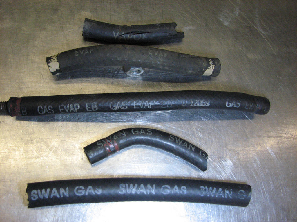
Just some of the many types of fuel and
evaporator lines you may encounter during your restoration. Keep your
original lines and replicate the markings if you so chose. Some of these
lines are available in the aftermarket while most you will need to replicate
the stamps and stamp your own. Many of these will also have date codes
on them.
Remove or cut the rubber fuel line(s) running from the frame mounted
fuel hard line to the fuel pump. If you are doing a concours restoration
just like any other facet of the disassembly, inspect the fuel line(s)
to see if they may be an original with ink stamping such as “SWAN
GAS” or “EVAP” so that these can be replicated during the restoration
process.
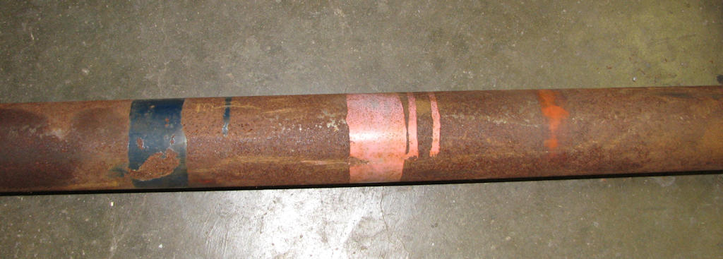
This is just one example of the stripes
that you may encounter on your drive shaft. The colors codes will be
found in box #19 of your 1970 build sheet and in this case marked PK-BL.
It is widely believed that the thin orange stripe denotes that the shaft
has been through the balancing process.
Remove the driveshaft at this time. Before doing so have a pan at
the ready and lay it underneath the transmission output shaft to
collect any transmission fluid that will leak. If not already done,
drain the engine oil at this time as well. Be aware that even more
anti-freeze, engine oil and transmission fluid may leak from these
areas as the engine and transmission are tilted up for removal.
This very driveshaft after restoration is later in the program.
Remove the four Universal joint U-bolts or through bolts, nuts
and straps, whichever your car has at the rear u-joint. Wrap duct
or electrical tape around the u-joint so that the bearing caps do
not fall off the u-joint and you lose some of your needle bearings.
Carefully set the rear end of the driveshaft on the ground (if you
are not using a hoist) then pull the front slip yoke from the transmission
tail housing. Place the driveshaft in a safe and secure area so
it does not fall as they can be easily dented. The u-joints will
be replaced later on in your restoration and we will cover that
part of the restoration at that time.
As always, make note of any markings you may find. The assembly
line shafts have paint stripes on them which correlated with box
#19 of a 1970 build sheet or box #22 of a 1971 or 1972 build sheet.
The assembly worker would look on the build sheet for the stripe
colors and would pick the correct shaft from the “bank” to install
on the car. Other paint markings can be found on the shaft as well
as the pinion flange and slip yoke so look around and photo document
them.
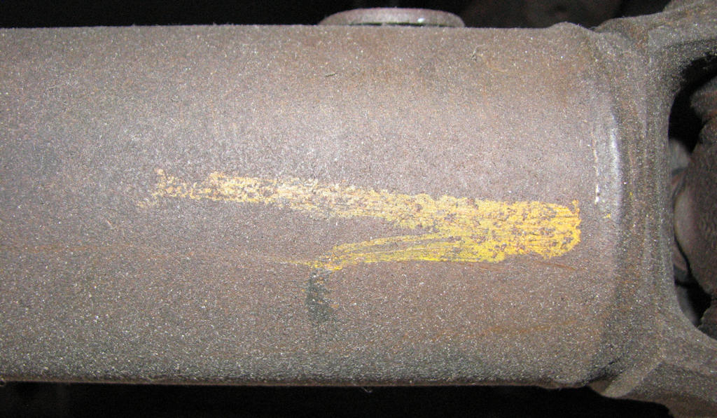
The author has yet to determine the
meaning of this yellow grease pencil marking on the aft part of
the driveshaft but has found it on many 454 shafts and always at
the rear. It is likely that it is just another way of marking that
a part of the machining or assembly has been completed and checked
or tells the installed to put that at the rear during installation.
Remove the carburetor and distributor as a safety issue so they
are not damaged during the engine removal process. Have an engine
stand, dolly, old tire, wood blocks or whatever else you intend
to use to set the engine on at the ready. It is recommended
to use an engine hoist or cherry picker as some are called,
to remove the engine and try to have a buddy available to help
negotiate the engine and transmission from the frame if needed.
Always, always use grade 3 or higher bolts and a chain suited
for the task. This is one area you never want to skimp on when
it comes to safety. Lift the engine and transmission from the
frame as a unit for ease of removal. Once on the ground the
engine and transmission can be separated. At this point the
transmission can be placed in a safe place preferably on a dolly
and the engine mounted on a stand to ease in its disassembly.
Chapter 4 - Chassis, Suspension, and Brakes
© Chevelle Restoration
|
 |