Chassis, Suspension, and Brakes
Parking Brake Removal
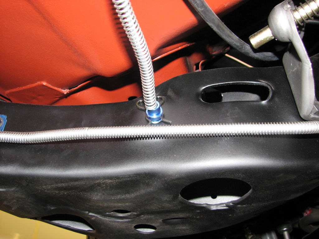
The primary parking brake cable will come
through the front frame rail just behind the driver’s front tire on
the rear side of that rail. After the intermediate cable equalizer and
large “C” hook have been removed, go back and remove the small “butterfly”
clip.
The parking or emergency brake (as it is commonly called) cables can now be removed and are in three separate assemblies. The front main cable which was already separated from the body during the body removal section in Chapter 3 can now be removed from the frame. Note that the cable comes downward and into the front corner of the driver’s side frame rail. From there it runs through a hole at the rear portion of that part of the frame and is held there by what is commonly called a butterfly clip.
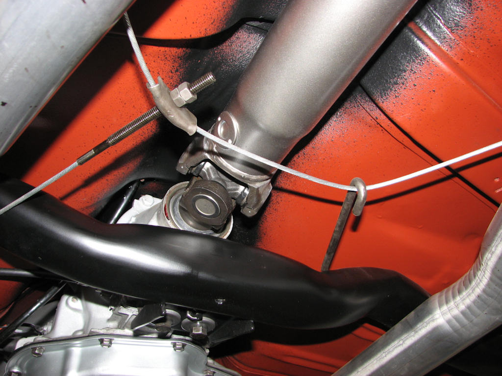
The primary cable attaches to the intermediate
cable by way of a stabilizer bracket and tension is applied via two
nuts. Remove these and the large “C “ hook from the intermediate cable
as well as the two smaller “S” hooks from the body and let the cable
drop. Move to the rear of the intermediate cable and remove the “U”
brackets.
Remove the intermediate cable from the equalizer and place the hardware and any other parking brake parts in the baggie you already had labeled from back when the body was removed from the frame. The two C shaped hooks that held the intermediate cable to the floor pan will already be in that baggie. Now that you have all of that hardware removed, go back and remove the butterfly clip from the primary cable and pull the cable upwards and out of the frame.
At the rear of the intermediate cable you will find two “U” brackets that hold the intermediate cable to the rear differential cables. Place the “U” brackets in your baggie and put the front main and intermediate cable in a safe place for restoration or replacement. Normally these cables are worn, stretched and rusted and will require replacement.
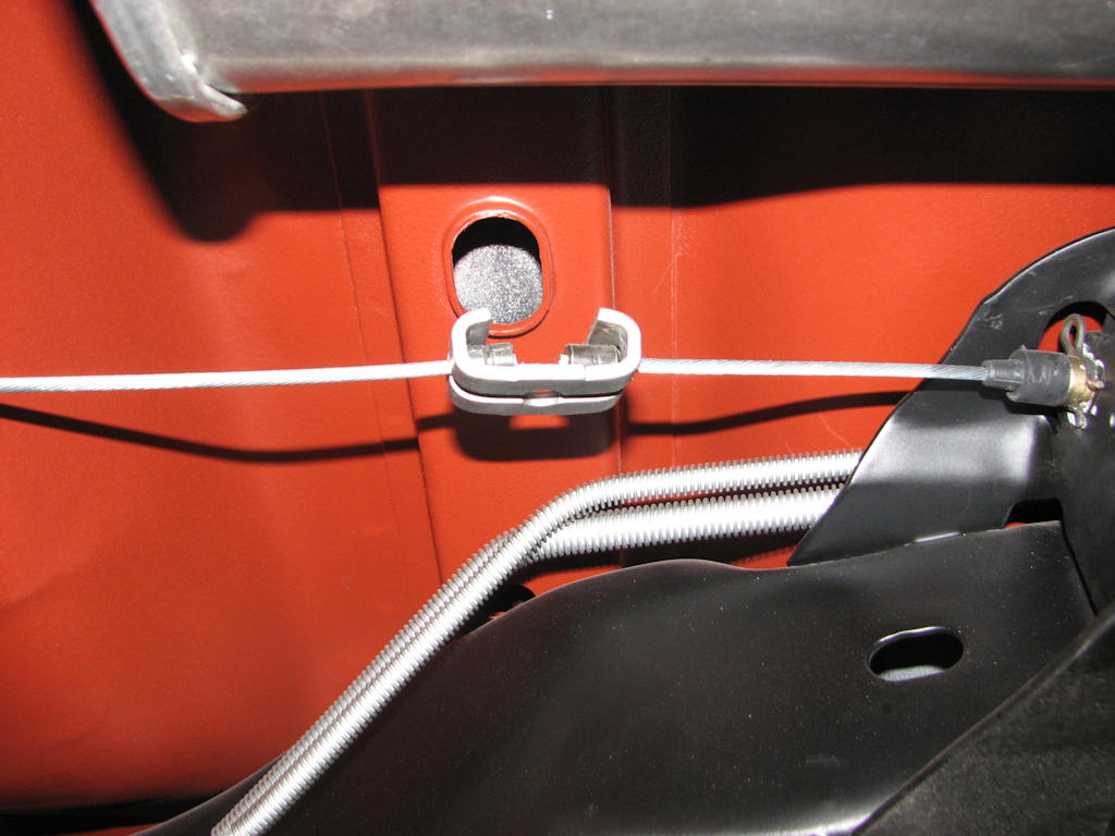
Moving to the rear of the intermediate
cable remove the “C” brackets that hold the intermediate cable to the
rear cable. Note that the rear parking brake cable is also held to the
frame with butterfly clips.
With the drivetrain and emergency brake cables out of the way, now
is a good time to remove the transmission crossmember. Chevrolet used
one type for manual transmissions and another for automatic transmissions.
The manual version had an additional bracket welded to the rear of it
for the manual shifter mounting bracket so make sure you have the correct
one. Also note how the four bolts are positioned that hold the crossmember
to the frame. The assembly manual states to install them facing downward
but some plants installed them facing up. Now would be a good time to
remove the transmission crossmember.
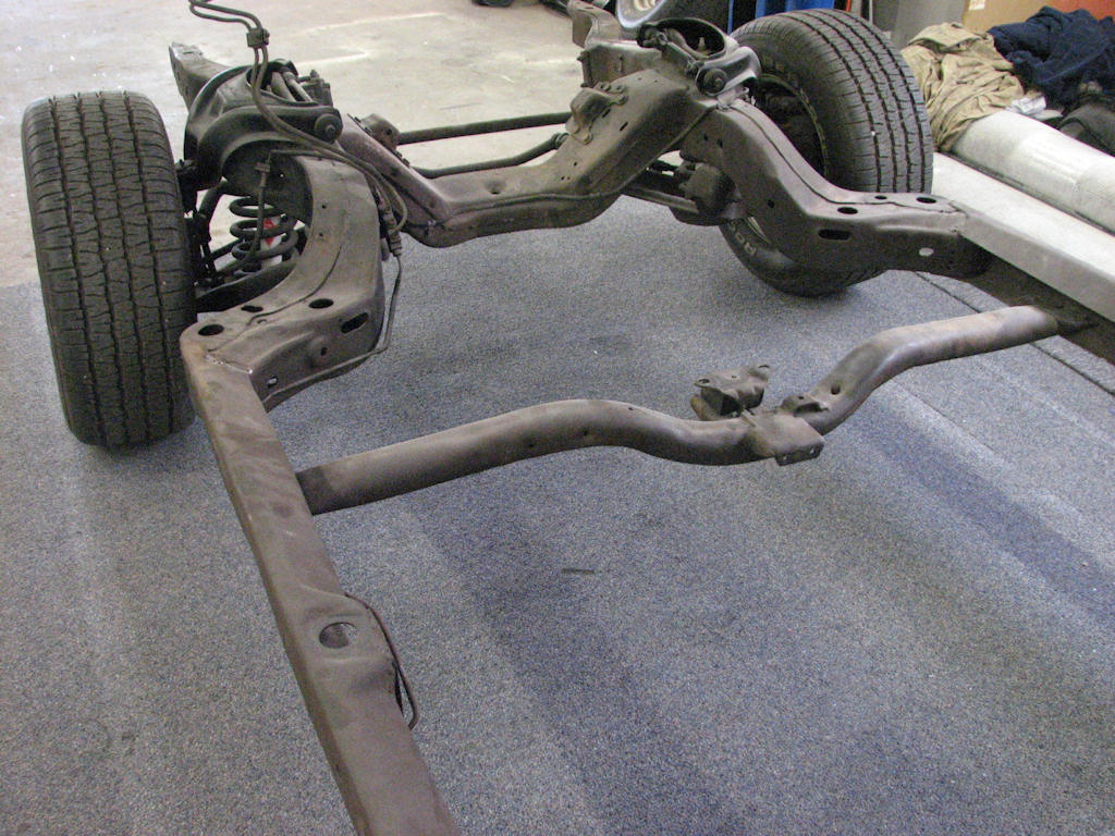
Determine if your crossmember is
correct for your application for the manual transmission (shown
here) or the automatic transmission. The manual transmission
crossmember will have the extra bracket welded to the rear of the
crossmember for mounting of the shifter bracket to it.
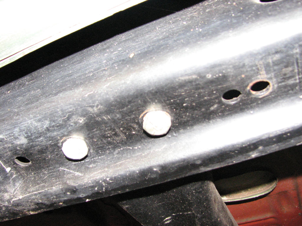
Pay special attention to the bolts
mounting the crossmember to the frame assuming they are original and
have never been molested. The assembly manual shows that these
should be mounted from the top down but the author rarely sees them
this way and are usually mounted from the bottom up. This is likely
due to the frame being assembled at the plant upside down.
| Chapter 4 - Chassis, Suspension, and Brakes © Chevelle Restoration |
 |