Chassis, Suspension, and Brakes
Drum Brake Removal
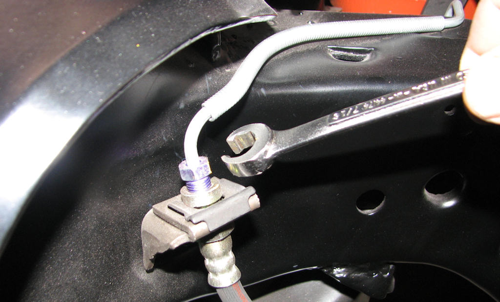
Use of a flare nut or line wrench here
is imperative as using a conventional wrench will only round the
edges of the nut ruining the fitting and making it much more
difficult to remove. Yet another good area to use a penetrant or
heat but as always be very careful not to burn the hose. The fluid
will also be extremely hot so care must be taken not to burn
yourself.
The spindle and brake assembly can be removed as a complete
assembly or as individual parts. It is actually better to remove the
assembly piece by piece so that you are using the frame as a jig to
hold the parts rather than wrestle with them on a bench. This will
also allow you to take better pictures if you find inspection marks,
decals or issues with the individual parts.
Drum brakes are slightly different in the disassembly process than
are disc brakes so both will be discussed here. On a front drum
brake assembly first remove the flexible brake line from the frame
mounting point using the appropriate sized line wrench. Not using
the correct tool here will cause you bigger headaches. Do the same
at the other end where it attaches to the wheel cylinder.
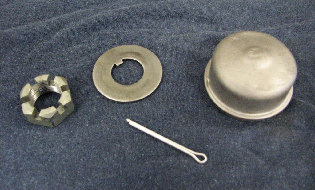
A dust cover will keep the bearing
free of dirt and moisture. It will also contain grease so that it
does not drip everywhere and contaminate the wheel. Behind the cover
you will find the nut, tabbed washer and cotter pin. Care must be
taken to not damage the spindle threads.
Move onto the brake drum. In some cases the shoes may have ground a groove into the inside of the drum due to excessive wear or the shoes may have also ‘welded’ themselves to the drum from sitting for so long. Both will inhibit easy removal of the drum and both of these situations can be a major headache. If the drum cannot be turned it is likely the shoes are stuck to it. You can try and dislodge them using a large rubber or plastic mallet and hitting the drum quite hard to try and loosen the shoes. It is very hard to get it inside the drum but spraying some penetrant so that it gets onto the shoes may also help loosen them. Sometimes there are adjustment holes that have been opened on the backside of the drum and it can be sprayed through there as well. In rare cases you may have to use a lot of heat and a sledge hammer to jar the drum free. However, using this method will most surely require replacement of the drum so use it as a last resort.
Once you have removed the drum you will see the spindle and bearing flange and the brake hardware. Remove the spindle dust cap using a dust cap removal tool or simply a large flat bladed screwdriver. Place the blade behind the raised ridge at the rear of the cap and walk the screwdriver around the cap and gently pry it loose without damaging the cap or flange. You will now see a large nut, washer and cotter pin.
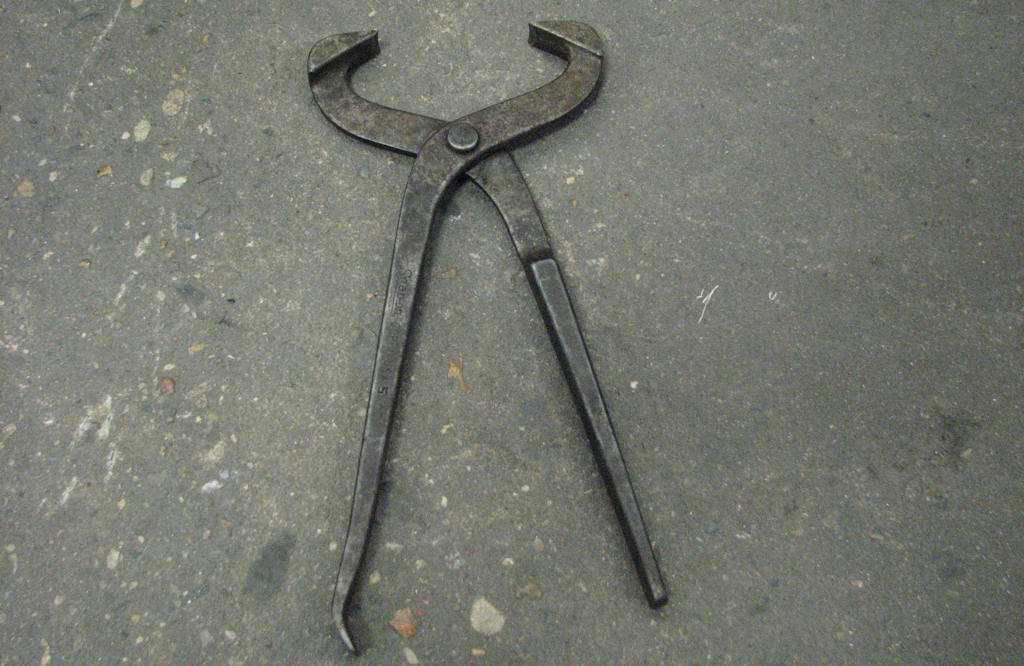
This tool can be used to remove the
spindle dust cover though a flat bladed screwdriver will also work
by simply walking it around the bearing cover. Using the dust cover
tool works by simply grabbing the cover behind the flange and
wiggling it back and forth. Place the nut, washer and cotter pin in
the dust cap and then into a baggie for safekeeping.
Remove the cotter pin by bending the tabs using a pliers and pulling the pin with either a pin puller tool or simply using a side cutter (dikes) and leveraging the pin out from its hole. In rare cases the pin may have rusted into the hole or break off and will require drilling the damaged pieces out. After the pin is removed, gently remove the nut using either a socket or crescent wrench. Using a gripping type of tool like a channel lock plies may damage the surface of the nut and is not recommended. Now simply wiggle the spindle flange and the outer bearing will walk out onto the spindle. Take a paper towel, grasp the bearing and set aside. While in this position a trick for removing the inner bearing and seal (if you are replacing the bearing) is to put the nut back on the spindle, pull the drum out until the nut contacts the roller bearing and while giving it a forceful tug toward you, the nut will force the bearing and seal from the back of the drum and spindle flange. It may require a few tugs before it separates itself. You can now remove the spindle flange/drum assembly.
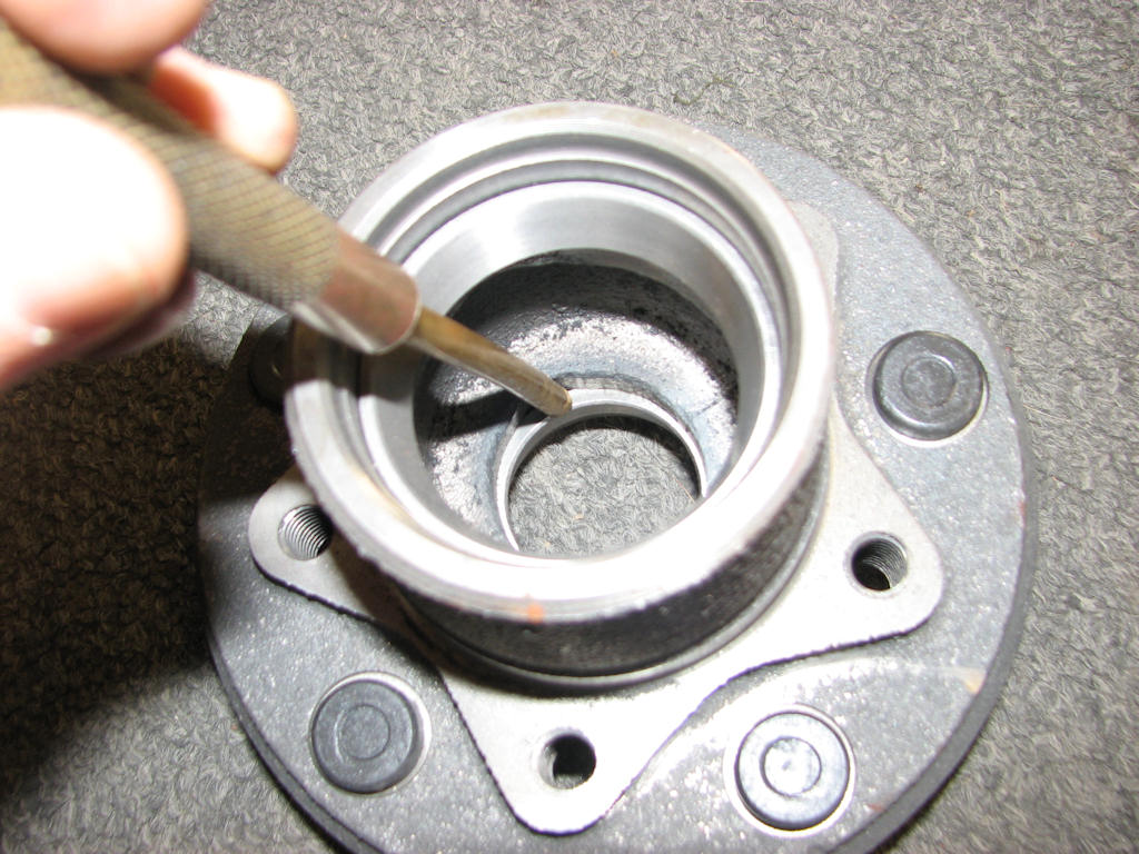
Using a brass drift and inserted
inside the bearing hub, place on the back side of the bearing race
in the relief cut out area within the hub. Gently tap this on both
sides and remove the bearing race being very careful not to damage
the mating surface of the bearing race.
Regardless of the type of restoration you are doing and at the very least, it is recommended to clean and re-grease the inner and outer bearings. Based on the cost and the fact that you are this far into it, replacement of the bearings and seal makes more sense. If you choose to clean and reuse your bearings you will still have to replace the inner seal on the backside of the drum and bearing hub. Before you decide to keep the bearing, clean them thoroughly and check for any roughness, expanded cages, missing bearings, etc. You will also want to clean the spindle off and check for any blued, galled or damaged areas where the bearing race rides as well as for bad threads on the shaft itself. Very minor damage can be massaged and cleaned up with emery cloth but damage beyond that will require replacement of the spindle itself. If you can feel a groove in the spindle with your finger nail, chances are the damage is too severe and replacement of the spindle will be necessary. If the spindle is badly blued it is also time to replace it as the bluing was caused by severe heat and this can cause the spindle to become brittle and break. If you chose to replace the bearings and/or drum and bearing hub you will also need to remove the bearing races in most cases as they should be matched to the bearings. Looking inside the drum mounting flange you will see the backs of the bearing races with only a very small cut out area for a driver tool to reach the backside of the bearing race. Using a small brass drift and small hammer very carefully drive the race out tapping from side to side until the race falls out being very careful not to damage the surface the bearing race lays against. Flip the rotor over and repeat for the other bearing race.
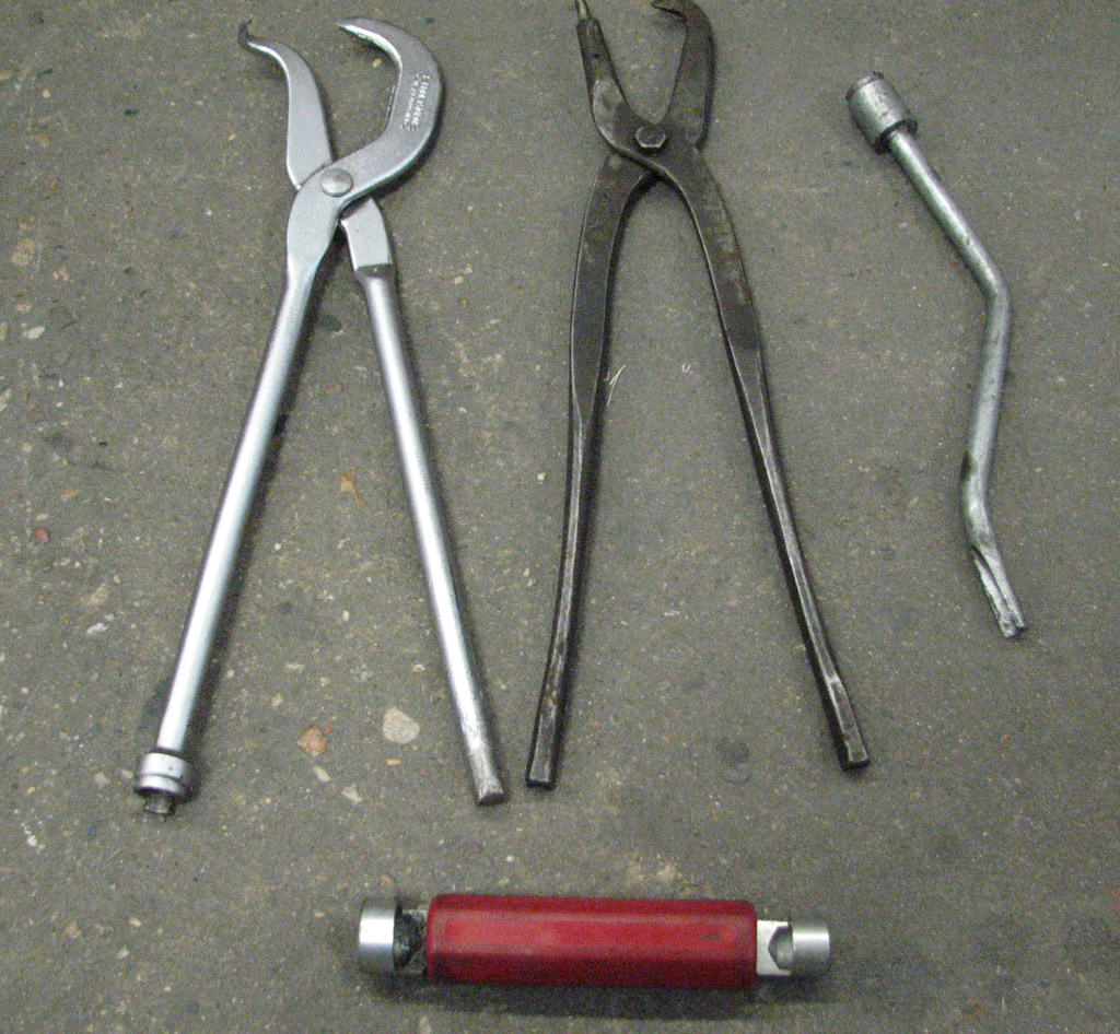
It is best to purchase yourself an
assortment of brake tools or buy them in a kit form as they make
doing brake work much easier and less chance of damaging the tool,
the part or yourself. It will also speed up disassembly and
assembly.
There are a variety of different brake tools available specifically for doing brake work. However, most standard every day tools in your tool box will work just as well to remove the springs, hardware, wheel cylinder and shoes. Once removed, place them all in a baggie or box and label them as to which wheel they came off of. You should now be left with a bare brake backing plate. Carefully inspect for cracks or other defects. Pay close attention to the pads on the backing plate where the brake shoes ride. If there is a grove cut into these pads, either replace the backing plate or weld the grove and grind flat as this will cause the shoes to hang up if left as is. At this point you can either remove the backing plate or leave it attached to the spindle or axle flange.
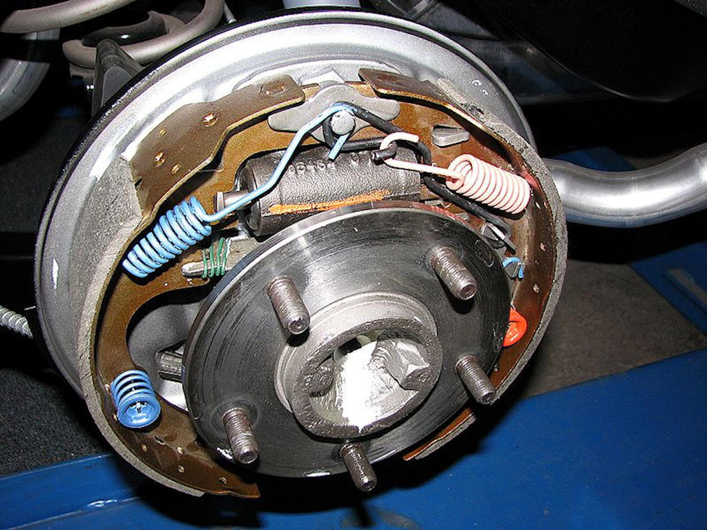
Drum brake rebuild kits come with
correct springs and clips to replace the well-worn units that came
on the car originally. Unless you happen to find a true survivor
that has never had the brakes replaced the colors of the various
components may vary.
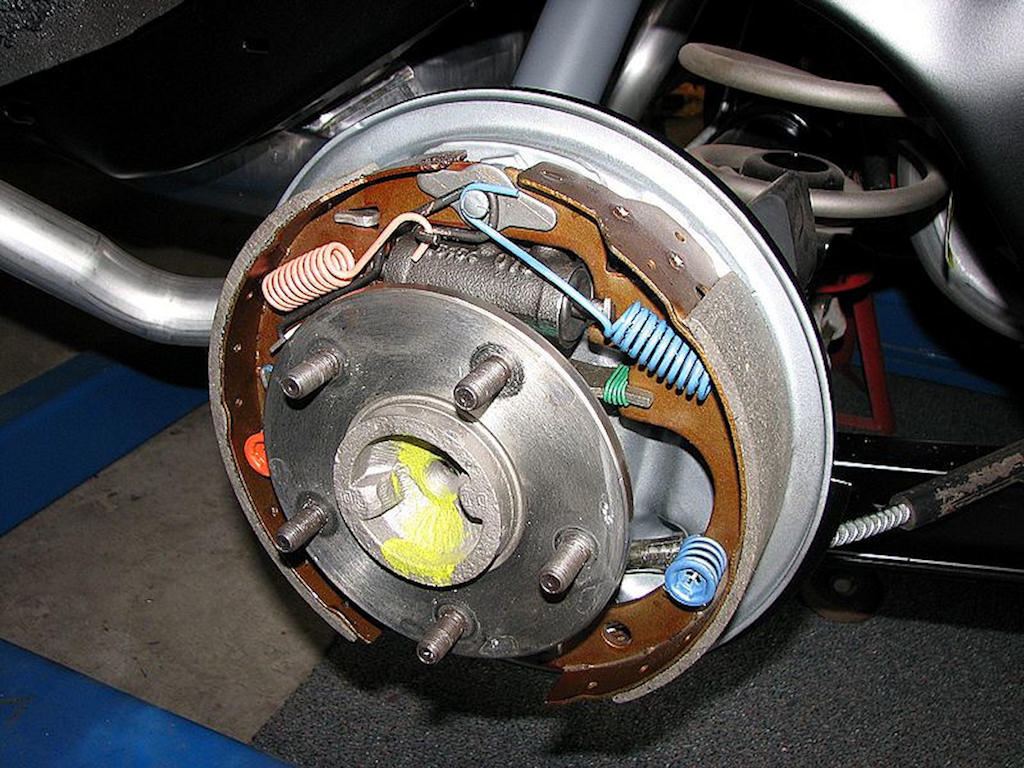
Note the difference in the surface
area of the front brake shoe compared to the rear brake shoe. Just
like the front disc or drum brake assembly, be sure to check the
threads on the wheel mounting studs for any sign of damage from
over tightening or cross-threading.
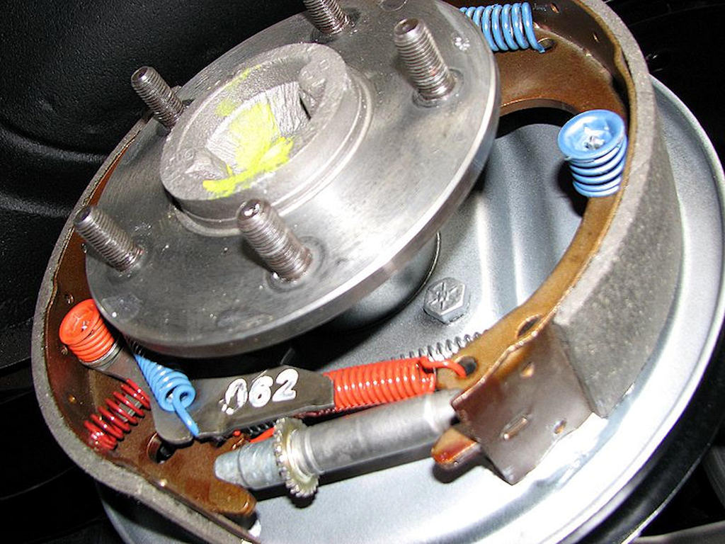
Be sure to install the self-adjusting
assembly correctly with the self-adjusting lever. Failure to install
it correctly will result in your brakes constantly needing manual
adjustment for good operation. Note the paint daub on the end of the
axle itself. The color may vary from plant to plant depending on
their standard operating procedure.
| Chapter 4 - Chassis, Suspension, and Brakes © Chevelle Restoration |


 |