Chassis, Suspension, and Brakes
Disc Brake Removal
Much of the removal process is the same as the drum brakes with minor exceptions. Starting with the caliper, remove the flex line from the frame mount as before, then onto the caliper side where the banjo bolt holds it to the caliper using a copper washer on either side of the line. Take caution as these lines are full of brake fluid and will damage paint if spilled. Look for and remove the two long internal 3/8” headed bolts that hold the caliper onto the caliper bracket. Loosen these until they no longer thread out, then pull them the rest of the way and set aside. Check for damage or excessive wear at the head and along the shaft of the bolt and set aside. The caliper is now free but due to the piston being forced out against the brake pads it may still not want to come off the caliper. Using a medium sized pry bar or large screw driver, pry the caliper back and forth against the rotor face in an attempt to force the piston back giving it more wiggle room to be removed from the rotor. Now place the same tool between the outer race of the rotor and the caliper on both sides of the caliper bracket. Gently pry upwards on both ends to pull the caliper up and away from the rotor. Once removed, the caliper assembly can now be set in a drain pan until it has fully drained.
Onto the spindle hub, remove the bearing dust cap from the face of the rotor hub. You can now see the cotter pin, nut and washer that are attached to the spindle. Remove these allowing the rotor to be freed from the spindle. Regardless of the type of rotors, place the palms of your hand on either side of the rotor and gently wiggle or push inwards. This will cause the outer bearing to come out of the spindle where you can now be able to grab and remove it. Set aside. As stated earlier in the drum brake removal section, while in this position a trick for removing the inner bearing and seal, and if you are replacing the bearing, is to put the nut back on the spindle, pull the rotor out until the nut contacts the inner roller bearing and while giving it a forceful tug toward you the nut will force the bearing and seal from the back of the rotor and/or bearing hub. It may require a few tugs before it separates itself. The rotor will now come off the spindle and can be placed aside.
On early 1970 Chevelles they used what is referred to as a two piece rotor. In this case the machined rotor can be separated from the bearing hub and can then be replaced or re-machined without doing anything to the bearings or hub other than unbolting it from the rotor which is not the case on a one piece rotor. In both cases and after the caliper has been removed and out of the way, the rotor (1 piece) or rotor/hub assembly (2 piece) is simply removed and separated from the bearing hub and can be set aside at this time. You will need to determine if the rotor is within spec or if it needs to be turned. If not enough material remains on the rotor face a replacement will need to be located and can be sourced from multiple places such as restoration parts suppliers. In the case of the one piece rotor it will have to be machined as a unit and as with the two piece rotor if there is not enough material left to machine it will need to be discarded and replaced as a unit.
Removing the bearing hub on two piece rotors is done the same way. The inner and outer bearing races, the inner bearing and the seal will all stay within the hub unless you use the seal removal trick stated earlier. The bearing hub can then be separated from the rotor by removing the five bolts attaching the rotor to the hub. If you did not remove the inner bearing and hub using the trick before, do so now by placing the rotor and/or hub face down on the floor and using a seal removal tool or another device that works gently pry up on the seal and remove it.
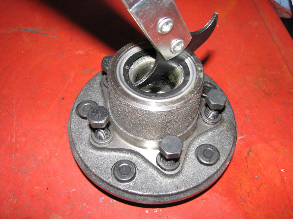
Using a seal puller in the manner
shown, gently pry up on the bearing seal with the removal tool while
walking around the circumference of the seal. If a seal removal tool
is not available a large flat bladed screwdriver can also be used.
Regardless of what tool you use the seal must be replaced.
If you are doing a more thorough restoration and replacing the bearings and/or rotor you will also need to remove the bearing races in most cases. It should be mentioned again that during a restoration it is best to replace the bearing as opposed to cleaning and repacking but that is up to you. If you insist on using the original bearings, thoroughly clean them of all grease and dry them off. DO NOT use an air hose and spin the bearings as this can not only damage them but they can also explode the cage and severely injure you. If you turn the bearing and do not feel any roughness or excessive looseness then grease and reinstall after the rotors have been restored or replaced.
As already covered in the drum brake removal section, look inside the rotor mounting flange (on two piece rotors) or the rotor itself (on one piece units), you will see the backs of the bearing races with only a very small cut out area for a driver tool to reach the bearing race. Using a brass drift and small hammer very carefully drive the race out tapping from side to side until the race falls out. Flip the rotor over and repeat for the other bearing race.
Before removing the spindle, loosen and remove the two bolts at the bottom that go through the backing plate, spindle and out the steering arm. Also remove the top center bolt holding the backing plate onto the spindle. The disc brake caliper bracket is also attached with these same bolts and can be removed at the same time. Once all are removed the steering arm, backing plates and caliper bracket can be removed and placed out of the way. Each of these items has to be put back on their correct side during reassembly.
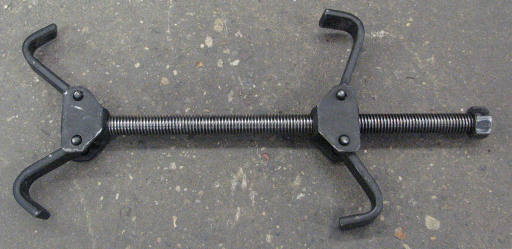
Get yourself a conventional coil
spring removal tool. These are readily available at most automotive
parts stores and can be rented from most of them as well as rental
shops. This will make coil spring removal and installation much
easier.
Now comes the interesting part, removing the front coil spring. It is best to use a spring compressor designed for this very job and there are several varieties on the market that can be used. It is also best to wrap a chain or strap around the coil and attach it to the frame to stop the spring from flying out and striking you if something goes awry. A ratchet strap with a hooked end also will do the job. Once you have the coil spring compressor installed remove the cotter pins from the upper and lower ball joints. Loosen the nuts several threads but be very cautious and leave enough threads attached to hold the nut on the spindle as the coil spring is under a great deal of tension.
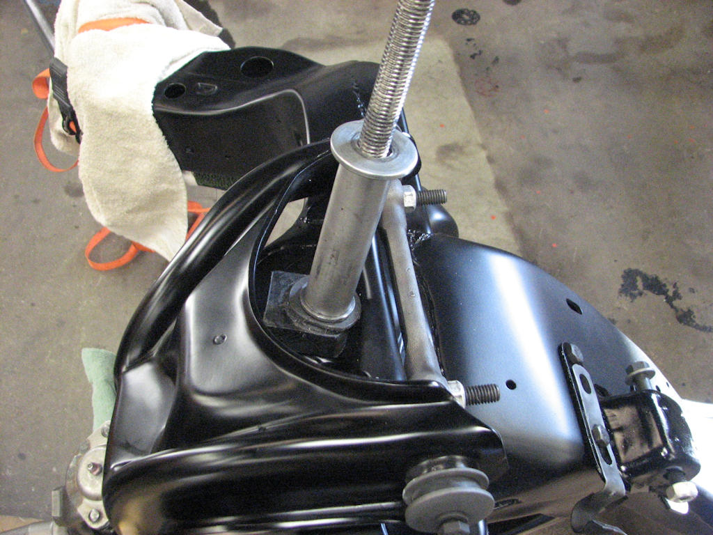
If you are more of a fabricator you
can also make your own took consisting of a stainless steel all
thread rod, steel spacer, phenolic spacer, washer, bearing and
bottom coil spring retainer from a conventional spring compressor.
This makes the job far easier and is much safer to use.
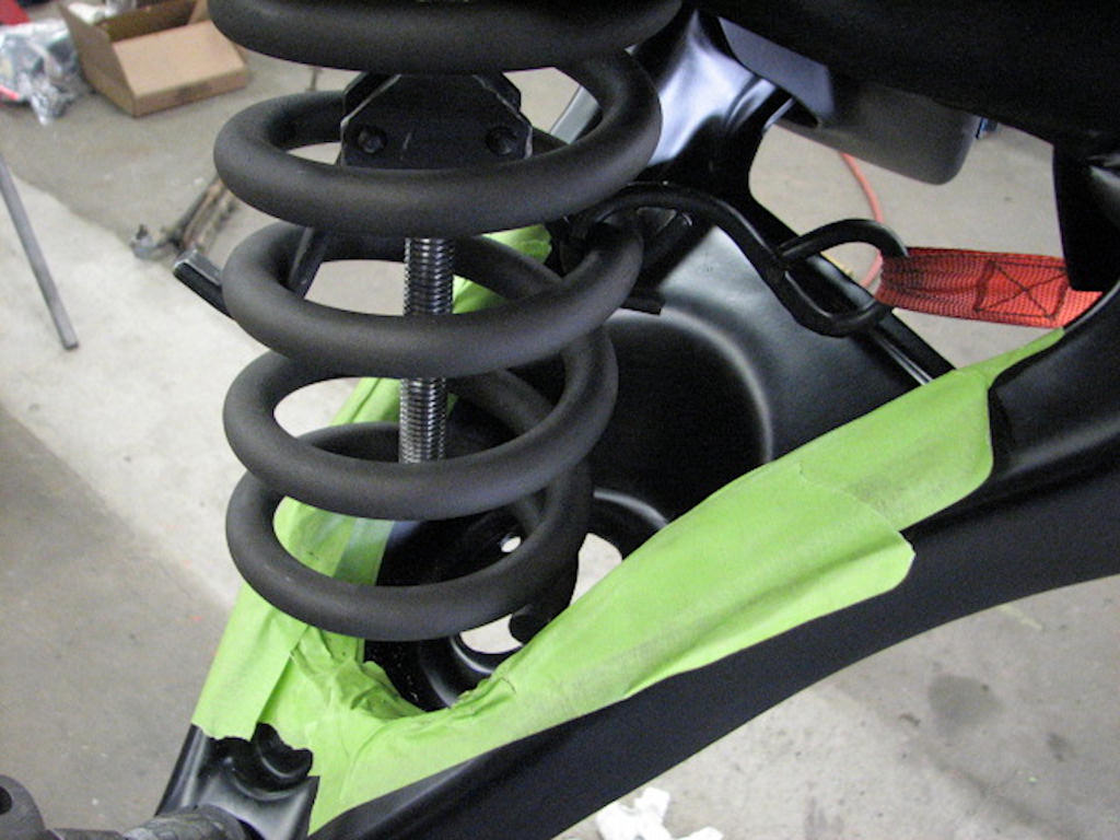
With this homemade tool, it not only
makes the job easier but the through rod helps hold the coil spring
in place in case of accident. The use of a hooked ratchet strap will
also greatly aid in the removal and installation as well as add to
the safety factor.
You can also have a tool fabricated similar to what the author uses which consists of a stainless steel threaded rod which is inserted through the upper shock mount hole. It should consist of a long stainless threaded rod, long tubular spacer, a phenolic spacer to protect the control arm, washer and a roller bearing that works very well to compress the spring. At the bottom of the threaded rod you can use the lower spring retainer hook from a conventional spring compressor tool.
This has the same result as a normal spring compressor but is much easier to use and does not get in the way as much. It is suggested that you also hook one end of a ratchet strap to the coil spring and the other end to a part of the frame on the opposite side of the car so in case of a mishap, the spring will not fly out and hit you. It is also best to protect the area surrounding the coil spring on the lower control arm but this is more important during reinstallation.
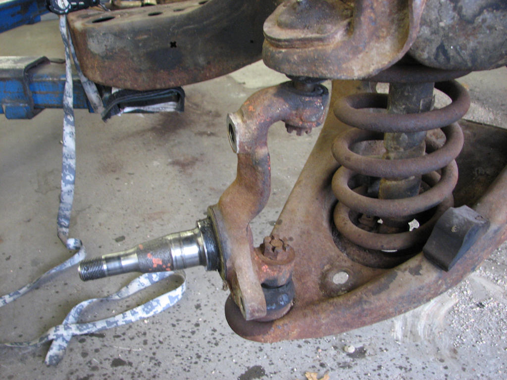
Notice how the spring tension has
aided the separation of the spindle from the ball joint stud
eliminating the need to impact the spindle with a hammer. Always
make sure you leave plenty of threads on the castle nut to retain
the spindle for the time being and so that it cannot completely
separate allowing the coil spring to fly off and cause bodily
injury.
Using the same tools and/or methods that you used to separate the tie rods, separate the spindle from the upper and lower control arms while leaving the spindle nuts slightly attached at this time. Often times applying some localized heat to the area of the ball joint stud will greatly help in separating the two from each other. During this procedure you may hear a loud bang and should notice that the spindle is now tight up against the nuts which means the ball joint studs have separated themselves from the spindle bore.
Using the spring compressor of your choice, compress the spring enough to take tension back off the spindle where it attaches to the ball joints. Once that tension has been removed, remove the nuts holding the spindle to the control arms and you are ready for the next step.
Depending on which method of overall restoration you are taking, you can also use several other tools and equipment to help here. If the body is still on the frame simply place a floor jack under the ball joint on the lower control arm. Using which ever method works best for you to separate the ball joint from the spindle, do so at this time using extreme caution. Once separated slowly lower the floor jack and allow the lower control arm to slowly pivot downwards allowing the tension of the coil spring to be gently released.
If you have a two-post hoist available and the body has been removed from the frame you can ratchet strap the frame to the hoist and secure it from moving and also use it as a tool. Lower the hoist all the way to the floor so that the lower control arms are resting on the floor. Once you have the spindle nuts loose you can separate the spindle from the ball joints. Once that takes place, very slowly raise the hoist letting the lower control arm stay resting on the floor allowing the tension on the coil springs to gently be released. Once again, it is suggested that you use a chain or ratchet strap around the coil spring to hold it from flying out. Once the spindle has been separated from the upper and lower ball joints remove it and place aside. Now you can remove the upper and lower control arms. Each lower arm is attached by two through bolts and lock nuts. Remove these followed by the arm. Be cautious as these are heavy and may drop out on their own when the bolts are removed.
Upper and Lower Control Arms Removal
The upper control arm is attached to the frame using two bolts on each side that run through the control arm cross shaft. Remove the lock nuts and wiggle the control arm towards the center of the frame and off the bolts. Slight tapping with a rubber mallet will help in the removal process. Remove the control arms and place aside.
If you are doing a full concours restoration you may want to consider removing the upper control arm attaching bolts from the frame and replacing them with new ones that are available from a variety of sources or if in good shape simply restore the originals. A few light taps with a hammer and pin punch will drive them out of the frame. Caution must be used as to not damage the threads.
Note that the head end of the bolt shank has knurling on it. This helps keep the bolt from spinning in the frame when you attach the lock nuts. New through bolts are usually good enough to keep them from spinning as long as the bolt holes in the frame are still good. If you have to reuse the old ones use a ball peen hammer and using the round headed part of the hammer hit the opening of the hole where the head of the bolt goes through on both sides of the opening. This will compress the metal slightly enough to give the bolt some bite when reinstalling it. You can also put a small tack weld on the head of the bolt at the frame but this is usually not necessary. As with any part of a restoration, always wear gloves as well as face and eye protection.
After all the pieces have been removed from the upper control arm, check for any damage such as a bent arm, damaged bushing holes, damaged rivet holes for the ball joints, etc. There is no point using the control arm if it has severe damage and will require a replacement. If there is only minor damage and you possess a welder than small repairs may be made. It is very common on the upper control arms to have bushings that are so worn that the cross shaft will have actually worn a grove in the bushing bore of the control arm. If not severe, this can be welded up and repaired. If these are extremely worn then it will again require replacement of the arm. Also check the cross shaft for severe damage as they too would need to be replaced.

As with any part of your restoration
examine all of the component parts for damage. Minor damage can be
repaired with a welder and grinder but if the damage is too severe
it may require replacement of the entire control arm. Also check the
cross shaft for damage.
Check the cross shafts as well to insure they are not replacement offset shafts. Offset replacement shafts would have been used if there were severe frame or suspension damage that had occurred and the repair shop chose to replace the shafts in order to get the car in alignment rather than replace the control arm or repair the frame. Assuming you will be repairing those areas during your restoration it will now make these offset cross shafts no longer necessary and a set of originals will need to be obtained.
Going back to the lower control arms, check them over thoroughly as well for any signs if damage. The most common signs are bent arms due to contact with a curb or other low obstructions that were encountered. Minor bending of the arm flange can be heated and repaired but severe bending will require replacement of the arm as it will be difficult to ever get the car aligned again. Severe bushing damage here is not as common but should be checked regardless. Ball joint bore damage is also somewhat common so look closely at that area as well. Most damages can be repaired using heat and a welder. As with many other parts of the restoration, replace all the bushing found on the suspension as these are inexpensive replacement items and now is the time to do them.
Upper Control Arm Bumper Removal
Now that you have all the front suspension out of the way, remove the upper control arm bumpers found underneath where the upper control arm had been mounted. These will need to be replaced. Simply pry them from the frame.
| Chapter 4 - Chassis, Suspension, and Brakes © Chevelle Restoration |
 |