Engine and Driveline
Evaporation Control System (ECS)
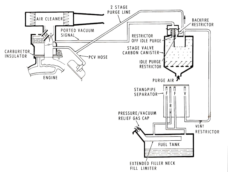
The Evaporation Control System (ECS) was introduced in 1970 for vehicles originally sold in California. The Federal Government required all passenger cars and light trucks with a gross vehicle weight of less than 6,000 pounds must be equipped with some form of ECS beginning in 1971.
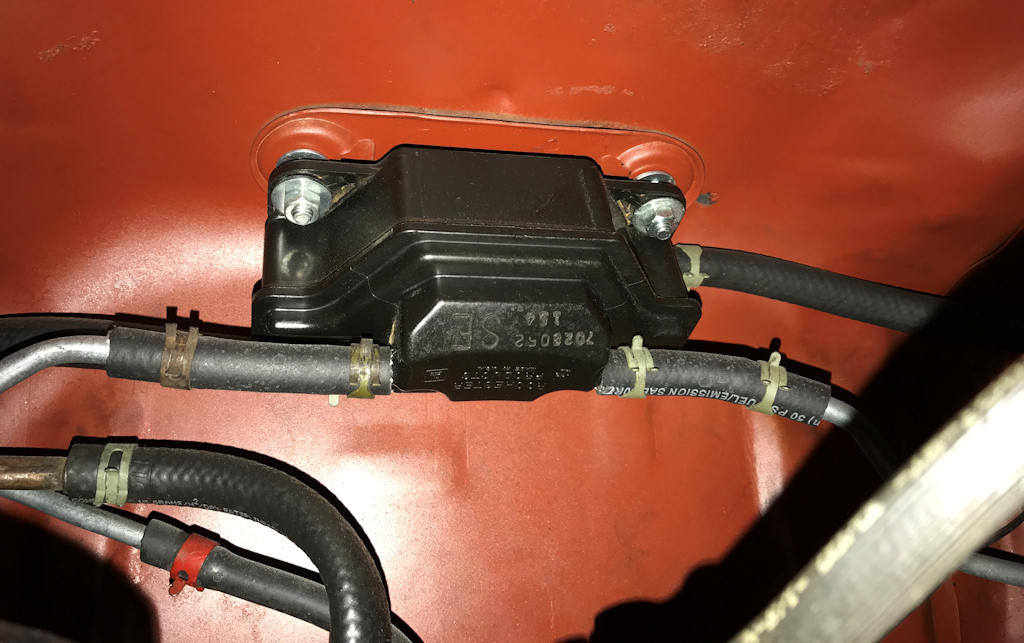
Part of the Evaporation Control System (ECS) introduced in 1970
for cars sold in California is the separator assembly located just
above the fuel tank. On a Van Nuys build sheet this is listed as
NA9. Although this car was built at the Arlington, Texas final
assembly plant, it was destined for a California dealer. - Mark
Wilson Photo
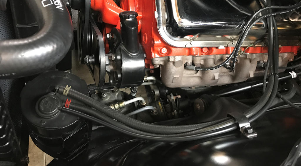
The second part of the Evaporation Control System (ECS) is the
canister located behind the radiator support on the driver’s side of
the engine compartment. Note the PCV valve has two connections; one
to the carburetor and one to the ECS canister. - Mark Wilson Photo
Since liquids, gasoline in this instance, have a tendency to vaporize as temperatures increase they release unburned hydrocarbons into the air. When exposed to sunlight, a secondary reaction causes the unburned hydrocarbons are converted into a photochemical smog. ECS is designed to minimize the loss of vaporized gasoline.
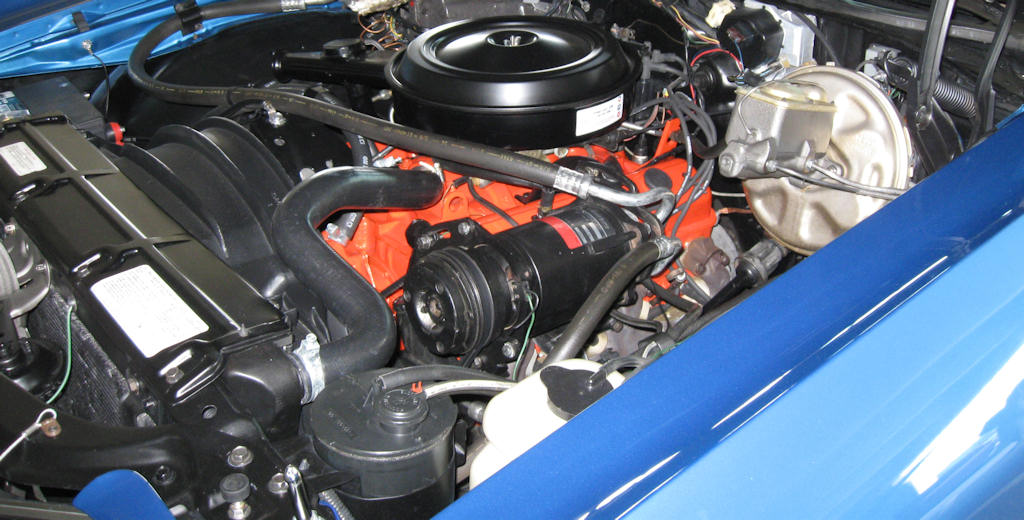
Evaporation Control System (ECS) canister shown here on a 1972 Monte
Carlo. Also note the correct lack of any engine size and horsepower
rating decal on the air cleaner lid.
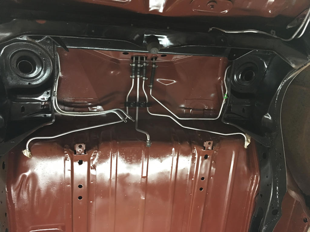
The routing of the numerous fuel and vapor lines on this 1972
Chevelle for the Evaporation Control System can be a challenge to
get correct. The red oxide paint color for the underside of the body
is common for Arlington, Texas-built Chevelles. - Manny Bustillo
Photo
Since the fuel tank is a part of the ECS the fuel level was reduced by lowering the filler neck from the highest point of the tank by about one inch. This allows more room for expansion and vapor collection on top of the gasoline. A vapor separator assembly would send the vapor back to the engine compartment via check & relief valve to a vapor storage canister containing approximately 1-1/2 pounds of charcoal.
The various assembly plants had their own standard operating procedure about how emission equipment was shown on their respective build sheets in 1972. The Baltimore, MD. and Kansas City, MO. final assembly plants would indicate the broadcast numbers as FUEL LINES on the various fuel pipes and describe the A.I.R. system as K19 EXH EMISSIONS on their 402 and 454 CID engines.
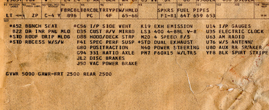
Lower section of 1972 build sheet from the Baltimore, Maryland
final assembly plant for LS3 engine showing K19 EXH EMISSION
verbiage and gross vehicle weight to show the car is in compliance
with federal regulations.
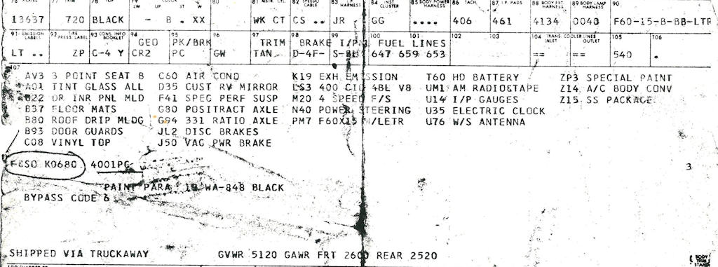
Lower section of 1972 build sheet from the Kansas City, Missouri
final assembly plant for LS3 engine showing K19 EXH EMISSION
verbiage and gross vehicle weight to show the car is in compliance
with federal regulations.